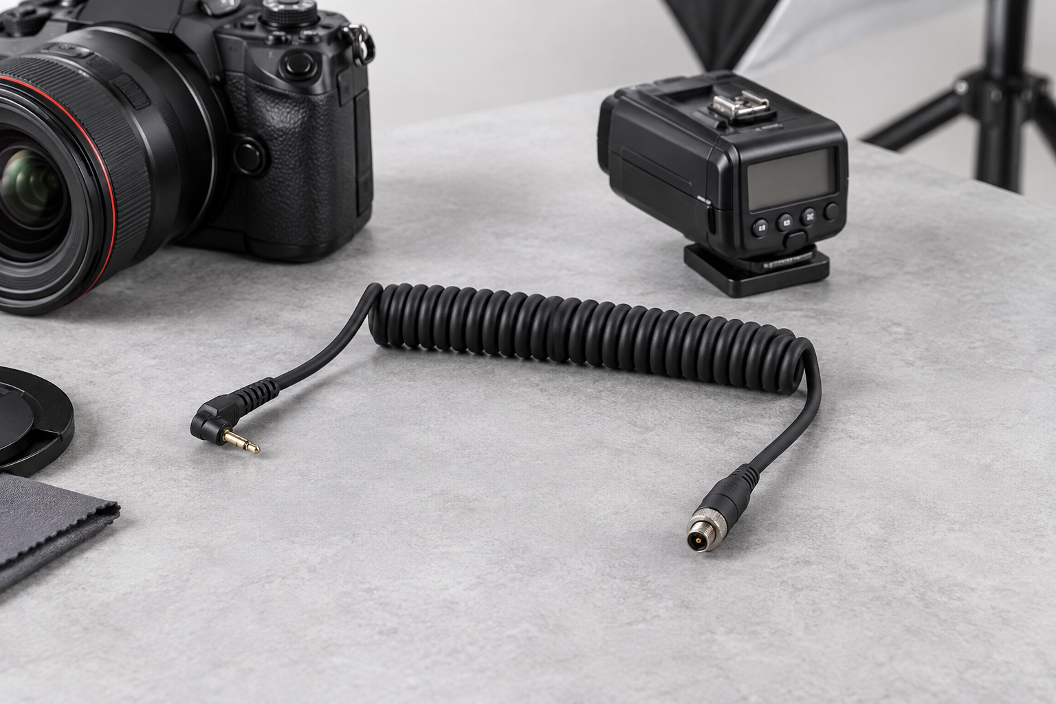
Quick Answer: A camera shutter coiled cable should transmit the trigger or synchronization function reliably without pulling a lightweight camera, flash or handheld controller out of position. Before sampling, confirm the equipment interface, contact sequence, connector orientation, relaxed length, normal working reach, straight-tail direction and the maximum acceptable return force.
Why Buyers Specify a Camera Shutter Coiled Cable
Coiled cables help keep excess cable away from tripods, studio work areas and handheld controls while still providing temporary reach. The electrical circuit may be simple, but the mechanical behavior is not. A coil that is too stiff can rotate a small camera, move a flash unit or place repeated load on a compact connector. A coil that is too loose may not retract into the intended storage area.
The correct design starts with the actual device and operating movement. Buyers should not approve the cable from an unconnected bench measurement alone. Review the sample on the intended camera, flash, remote trigger or controller.
Specifications to Confirm Before RFQ
| RFQ item | What to provide | Why it matters |
|---|---|---|
| Equipment interface | Camera, flash, remote or controller model | Confirms mating connector and operating context |
| Trigger function | Contact sequence, pinout and normally open/closed behavior where applicable | Prevents an electrically incompatible sample |
| Relaxed length | Coil body and straight-tail dimensions in the stored position | Controls storage and cable routing |
| Working reach | Normal operating extension, not only a maximum pull length | Defines usable movement and return force |
| Connector exit | Straight, angled and orientation requirements | Reduces sharp bending near compact connectors |
| Shielding | Required only when supported by the circuit and equipment design | Avoids adding an undefined shield termination |
| Quantity and packaging | Sample quantity, forecast, labels and unit packing | Affects tooling, production planning and quotation |
How Should Working Reach and Return Force Be Approved?
Define the normal distance between the two connection points during operation. The sample should reach this distance without approaching a hard extension stop. Then observe whether the cable pulls, rotates or lifts the connected device. For lightweight equipment, this practical movement check is often more useful than specifying only a nominal extension ratio.
Record the relaxed coil length before extension, the normal working reach, the straight-tail lengths and the recovery condition after repeated manual use. The buyer and supplier should use the same measurement method. See the TPU coiled cable working reach and connector-load guide for additional review points.
Connector, Pinout and Cable Exit
Small camera and flash connectors can look similar while using different contact assignments or keying. Provide connector part references, clear photos of the mating interface and a pin-to-pin drawing whenever possible. If the connector is molded or overmolded, confirm the required exit direction before tooling or sample production.
The straight tail should prevent the first coil from rubbing against the enclosure or applying a sharp bend at the connector. Review the strain relief and overmolding checklist when the assembly uses molded connector exits.
Sample Approval Checklist
- Verify pin-to-pin continuity against the approved drawing.
- Confirm the trigger or flash synchronization function on the intended equipment.
- Check connector mating depth, orientation and retention.
- Measure relaxed length, normal working reach and both straight tails.
- Observe whether return force moves lightweight equipment.
- Inspect cable exits and strain relief during normal movement.
- Confirm recovery and storage after repeated extension by hand.
- Approve labels and packaging against the purchase specification.
Common Mistakes That Delay Sampling
- Sending only a connector photo without a part reference or pinout.
- Using maximum stretched length as the normal working reach.
- Ignoring the return force applied to a small camera or flash unit.
- Leaving connector exit direction until after the sample is built.
- Requesting shielding without defining how the shield is terminated.
- Approving continuity but not testing the actual trigger function.
Buyer Checklist
- Equipment model and application
- Connector references and mating interface photos
- Pinout and trigger or synchronization function
- Relaxed length, working reach and straight tails
- Preferred coil direction, color and cable exit
- Shielding or grounding requirement, if applicable
- Sample quantity, annual demand and packaging
What to Send in the RFQ
Send the drawing, equipment model, connector information, pinout, normal working reach, relaxed storage space and sample quantity. If the drawing is not ready, send clear device and connector photos plus the required function. Nexharn can review the information before a sample route is confirmed.
Review the camera shutter and flash sync coiled cable product page, compare all custom TPU coiled cable options, or upload your RFQ and sample requirements.