
Quick Answer: A drone ground controller coiled cable should be designed from the exact circuit function and operator movement, not from coil length alone. Buyers should define whether the cable carries power, control signals, telemetry or combined circuits, then confirm conductor layout, shielding and grounding, connector locking, relaxed length, working reach and sample acceptance checks.
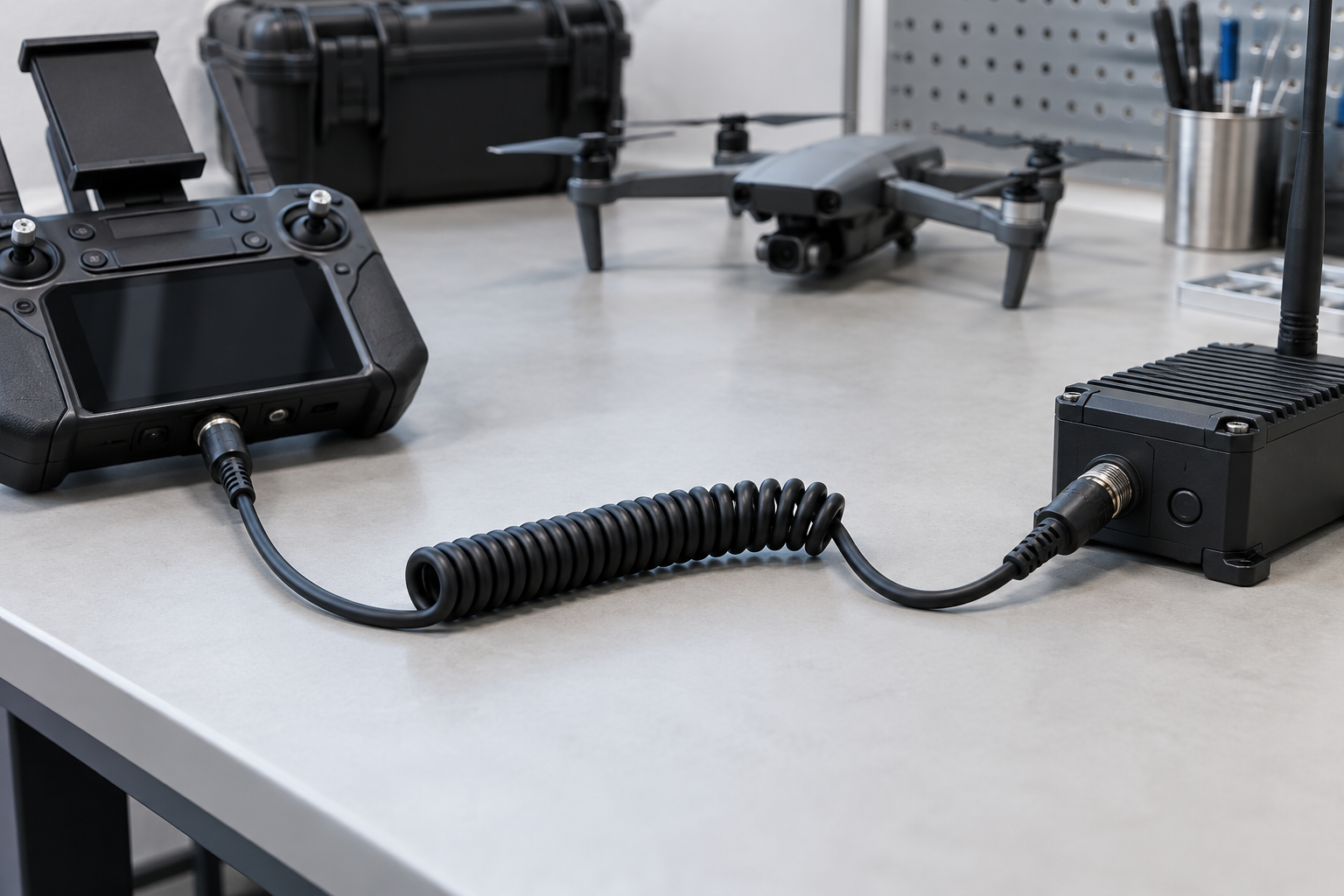
Why Ground Controller Cables Need a Circuit Review
Ground-control equipment may connect a handheld controller, display, antenna unit, telemetry module, charger or vehicle-mounted station. These interfaces do not all use the same electrical construction. Some need only low-voltage power, while others combine data, control and power conductors. A quotation based only on an outside cable diameter or a connector photo can miss the conductor layout and grounding requirements.
Start the RFQ with a circuit list and pinout. Identify signal pairs, power conductors, returns, shields and any reserved contacts. This gives the cable manufacturer enough information to review conductor grouping and sample tests.
Specifications to Confirm Before Sampling
| Specification | Buyer input | Sample check |
|---|---|---|
| Circuit function | Power, control, data, telemetry or combined use | Verify each pin against the approved drawing |
| Conductors | Count, gauge, pairs and current requirement | Check construction and continuity |
| Shielding | Shield type, drain wire and termination at each end | Confirm shield and ground connections |
| Connector locking | Part references, keying and retention method | Test mating, orientation and normal movement |
| Working reach | Operator stance, mounting points and normal extension | Check reach without a hard pull |
| Straight tails | Length and exit direction at both ends | Inspect routing around controls and mounts |
| Field conditions | Indoor/outdoor exposure and customer specification | Agree applicable inspection or test plan |
Shielding and Grounding Questions
Shielding should follow the equipment design. State which circuits require shielding, whether pairs need individual or overall shielding, and where the shield or drain wire connects. A shield that is not terminated according to the system drawing may not provide the intended result. Do not rely on the phrase “shielded cable” without a termination plan.
Use the shielded TPU coiled cable EMI and grounding checklist to prepare these details. Final electromagnetic compatibility remains part of the complete equipment validation.
Connector Locking and Cable Routing
Field equipment can be moved, carried or mounted on a stand or vehicle. Confirm whether the connector uses a latch, thread, bayonet, push-pull or another retention method. The cable exit should not block switches, joysticks, displays or antenna mounts. Straight-tail length and orientation should be checked with the controller in its normal operating position.
A locking connector does not replace strain relief. Review the cable exit under the expected movement and confirm that the first coil does not repeatedly bend against the connector body.
Working Reach and Operator Movement
Define normal working reach from the installed connection points. Include the operator position, controller mount and any nearby obstruction. The sample should provide useful movement without reaching maximum extension during routine operation. Excessive return force can change the position of a handheld controller or place continuous load on the connector.
Measure relaxed length, normal extension and both straight tails using the same method for RFQ and sample approval. When reach is critical, consult the working reach and connector-load guide.
Sample Approval Checklist
- Verify pinout, continuity and conductor assignments.
- Confirm shield and drain-wire termination against the drawing.
- Test connector mating, keying and locking on the intended equipment.
- Measure relaxed length, working reach and straight tails.
- Observe cable pull during normal controller movement.
- Inspect strain relief and routing near controls and mounting points.
- Complete any buyer-defined functional or communication test.
- Approve identification, labels and unit packaging.
Common RFQ and Sampling Mistakes
- Describing the cable as “signal and power” without a pinout.
- Requesting shielding without defining grounding at both ends.
- Choosing a connector before checking locking and keying.
- Using maximum stretched length as the operating distance.
- Ignoring straight-tail routing around controller switches and mounts.
- Assuming the cable alone determines system-level environmental or EMC performance.
Buyer Checklist
- Controller and connected equipment models
- Circuit function, voltage, current and signal type
- Conductor count, gauge, pairs and shielding
- Connector part references, pinout and locking
- Relaxed length, working reach and straight tails
- Mounting, movement and field-use conditions
- Sample quantity, forecast, marking and packaging
What to Send in the RFQ
Send a cable drawing or wiring table, connector references, equipment photos, normal working reach, installation position and sample acceptance requirements. If the drawing is incomplete, identify the circuit function and provide clear photos of the mating equipment so the missing questions can be listed before quotation.
Review the drone ground controller TPU coiled cable product page, browse custom TPU spiral cable options, or send your drawing and RFQ details.