
Quick Answer
An EV charging signal coiled cable should be specified separately from the main high-current charging path. Buyers should define the auxiliary circuit function, voltage or signal type, conductor construction, connector and mating parts, pinout, shielding and grounding method, relaxed length, normal working reach, installation position and sample acceptance tests. A supplier cannot determine these requirements from the phrase “EV charging cable” alone.
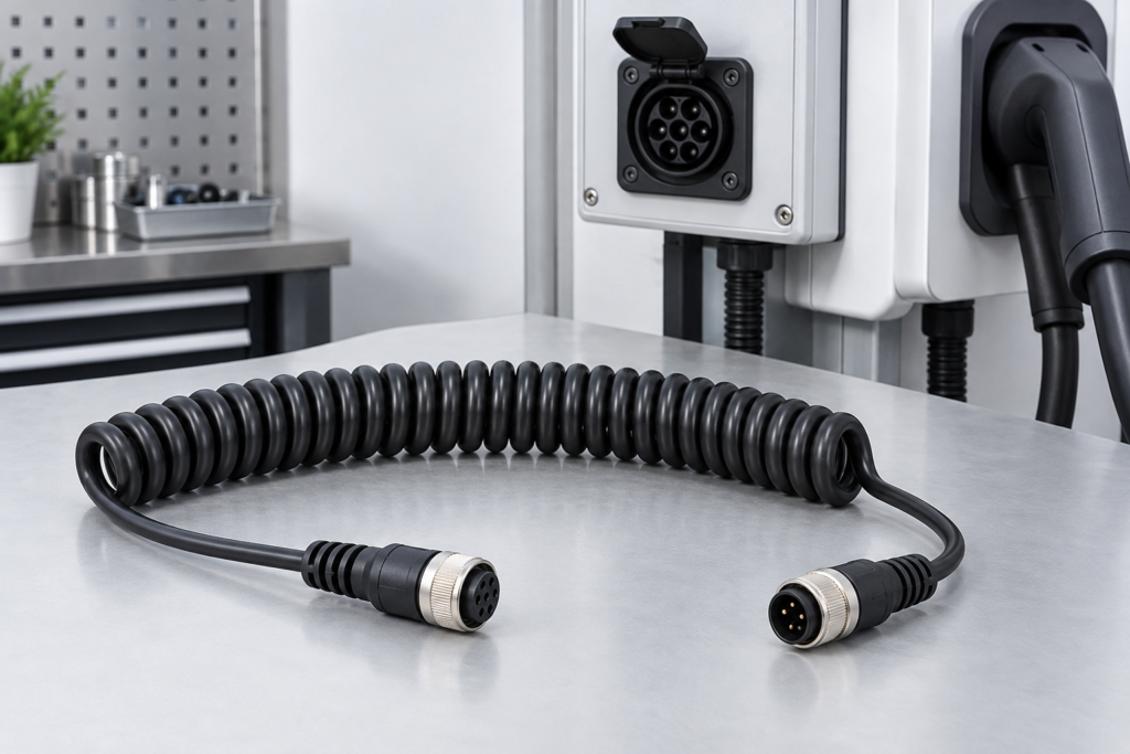
Start with the EV Charging Auxiliary Signal Coiled Cable product page and compare the wider custom TPU coiled cable range.
Clarify What the Cable Actually Does
The first RFQ question is whether the coiled assembly carries low-voltage control, communication, sensing or another auxiliary function. This article does not describe the primary traction or high-current charging cable.
Provide a functional description for every circuit. Useful inputs include:
- Control or signaling purpose
- Voltage and current requirement
- Communication or sensor function
- Number of conductors or pairs
- Shielding and grounding requirement
- Connection between the charging unit and auxiliary device
When the circuit is confidential, buyers can still provide a controlled pinout and electrical requirement under the agreed project process.
Why Coil Geometry Matters
An auxiliary lead may need to extend between a charging unit, holster, control interface or service device. The coil should remain compact when parked without placing unnecessary load on the connector during use.
Define:
- Relaxed coil length
- Normal working extension
- Temporary maximum extension
- Coil outside diameter and available storage space
- Straight-tail length at both ends
- Cable exit direction and routing
Working reach should be tested in the actual mounting arrangement. A bench measurement cannot show whether the cable interferes with a holster, door, enclosure or connector angle.
Pinout and Connector Information
Connector assumptions create expensive sample delays. The RFQ should include:
- Connector manufacturer and part number
- Mating connector or equipment interface
- Pin numbering and circuit assignment
- Keying and orientation
- Locking or retention method
- Cable exit direction
- Overmold or strain-relief expectation
When an environmental sealing target applies, state the required test method and responsible approval level. A connector described as sealed does not automatically prove the complete cable assembly meets a particular rating.
Shielding and Grounding Review
Signal integrity depends on the actual circuit, cable construction, connector termination and equipment grounding arrangement. Do not request “shielded cable” without defining how the shield should be handled.
Confirm:
- Overall shield, pair shield or no shield
- Twisted-pair requirement
- Drain wire requirement
- Shield connection at one end or both ends
- Connector shell or dedicated contact termination
- Equipment grounding reference
Use the Shielded TPU Coiled Cable EMI Checklist to document the intended termination. The final method should follow the buyer’s electrical design and sample evaluation.
Recommended RFQ Specification Table
| Item | Information to provide |
|---|---|
| Equipment | Charging unit, control device and installation position |
| Circuit | Control, signal, communication or sensing function |
| Electrical | Voltage, current and signal requirements |
| Conductors | Count, gauge, pairs and identification |
| Shielding | Shield type, drain wire and termination method |
| Connectors | Part numbers, mating parts, pinout and keying |
| Dimensions | Relaxed length, working reach, maximum extension and tails |
| Environment | Outdoor exposure, abrasion, liquids, cleaning and routing |
| Approval | Electrical, dimensional, mating and packaging checks |
| Commercial | Sample quantity, forecast, labels and packaging |
Sample Approval Checks
Before production, agree on the checks that apply to the auxiliary assembly:
- Continuity and pinout verification
- Project-defined voltage, insulation or signal checks
- Connector mating, keying and retention
- Shield continuity and termination inspection where required
- Relaxed length, working extension and straight-tail measurement
- Return-force and cable-exit observation in the installed position
- Appearance, marking, label and packaging review
Testing should follow the buyer’s circuit and equipment requirement. Do not substitute a generic cable test for complete charging-equipment validation.
Common Failure Modes to Review
Auxiliary and main-power requirements are mixed
Separate the low-voltage or signal assembly from the high-current cable specification. They have different design inputs and approval responsibilities.
Pinout is supplied too late
Connector availability and tooling may be reviewed before the circuit is final, but a production sample should not be approved without controlled pinout information.
Shielding is specified without termination details
An undefined shield can be connected differently from the equipment designer’s intention. State the termination method in the drawing.
Maximum stretch is used as working reach
This can increase connector load and reduce the cable’s ability to return to its parked position. Approve the normal reach separately.
Outdoor requirements are described only as “waterproof”
List actual exposure, connector interface, test method and equipment-level acceptance criteria instead of relying on a broad word.
Buyer Checklist
- Auxiliary circuit purpose
- Voltage, current or signal requirement
- Conductors, gauge and pairs
- Shielding and grounding method
- Connector models, mating parts and pinout
- Relaxed length and normal working reach
- Straight tails and cable exit
- Installation position and environment
- Sample acceptance tests
- Quantity, revision, labels and packaging
Supporting Evidence and Resources
Review the photographed custom coiled cable length inspection and packaging case for examples of visible dimensional and packing evidence. Download the TPU coiled cable RFQ and sample worksheets before sending the project.
What to Send in Your RFQ
Send the auxiliary circuit description, pinout, connector data, shielding method, dimensional drawing, installation photos, sample quantity, annual demand and packaging requirement. Clearly identify which values are fixed and which still require review.
Upload your EV charging signal coiled cable RFQ for a project-specific manufacturing review.