Quick Answer
A VR or AR headset coiled cable should be designed around the interface, data and power requirements, user movement, normal working reach, return force, connector orientation, shielding and strain relief. A compact coil can help manage excess cable, but too much pull, weight or stiffness can load the headset connector and affect user comfort. Approve the cable on the actual headset or controller setup before production.
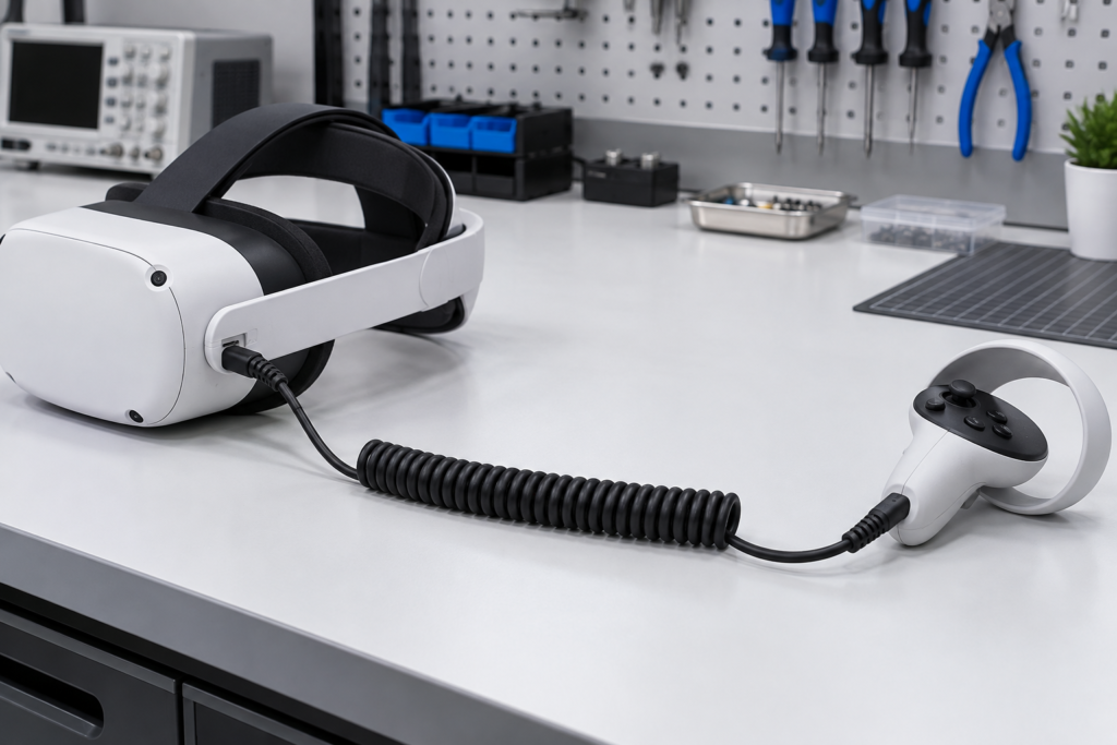
Review the VR / AR Headset and Controller Coiled Cable product page, then compare other custom TPU coiled cable options.
Begin With the Interface, Not the Coil
The phrase “VR cable” does not define the electrical construction. The cable may carry power, USB data, device-specific signals or a combination of circuits. Buyers should provide the connector models, interface requirement, supported function and equipment revision before a supplier recommends conductor or shielding construction.
Confirm:
- Headset, controller or training-equipment model
- Data, power, trigger or tracking function
- Interface and connector type
- Required conductor or pair arrangement
- Shielding and grounding method
- Fixed, replaceable or serviceable cable design
Do not infer bandwidth or charging performance from connector shape alone.
Map the User Movement
A coiled cable must support the intended movement without constantly pulling the device. Describe how the user stands, turns, reaches and returns the controller or headset to its parked position.
Useful inputs include:
- Distance between the user and equipment
- Normal movement radius
- Temporary maximum reach
- Cable routing above, behind or beside the user
- Fixed mounting, belt connection or suspended support
- Risk of rubbing against furniture, frames or equipment
The sample should be evaluated in the real routing path, not only extended in a straight line.
Define Relaxed Length and Working Extension
Buyers should separate storage dimensions from operating dimensions:
| Dimension | Why it matters |
|---|---|
| Relaxed coil length | Determines parked size and cable management |
| Normal working extension | Defines routine user reach |
| Temporary maximum extension | Helps review occasional movement without treating it as daily use |
| Straight tails | Controls the uncoiled section near the device and fixed equipment |
| Coil outside diameter | Affects available space, handling and return behavior |
Return force should be low enough for the equipment arrangement while still allowing the cable to recover toward its parked position. Final behavior depends on the complete construction and must be approved with a sample.
Connector Orientation and Cable Exit
Headset and controller connectors are often sensitive to cable angle and repeated handling. Provide:
- Connector manufacturer and model
- Mating device and port orientation
- Straight or angled exit
- Keying and insertion direction
- Retention feature
- Overmold dimensions
- Strain-relief length and flexibility
Check whether the cable exit touches the user’s body, blocks adjacent ports or creates leverage on the connector during movement.
Data, Power and Shielding Questions
The required cable construction depends on the electrical interface. Buyers should define the actual performance target and reference specification.
Questions to answer include:
- Is the cable power-only, data-only or combined?
- What voltage and current are required?
- Are controlled-impedance pairs required by the interface?
- Is an overall shield, pair shield or drain wire specified?
- How is the shield terminated at each connector?
- Is the connector shell part of the grounding design?
The supplier should build against an approved drawing or interface requirement rather than claim performance from the TPU jacket or connector name.
Weight, Drag and User Comfort
Coil geometry, conductor construction, jacket thickness, connectors and overmolds all affect weight and drag. For wearable or handheld equipment, review:
- Pull on the headset during normal movement
- Cable contact with the neck, shoulder or clothing
- Controller balance and cable exit
- Noise or vibration transferred through the cable
- Heat sources and skin-contact areas
- Storage behavior after use
User-comfort observations should be included in sample approval when the cable directly affects movement.
Sample Approval Checklist
Electrical and interface checks
- Continuity and pinout
- Project-defined power and data checks
- Connector mating and orientation
- Shield and shell termination where required
Mechanical and use checks
- Relaxed length and working extension
- Straight-tail length and exit direction
- Return force in the installed route
- Connector and strain-relief movement
- Interference with the headset, controller or user
Production and receiving checks
- Drawing and equipment revision
- Appearance and marking
- Packaging recovery after unpacking
- Label and variant identification
Use the TPU coiled cable strain relief and overmolding checklist when reviewing the device-side termination.
Common Sampling Mistakes
- Selecting the coil before confirming the interface
- Using maximum stretch as the normal working distance
- Omitting connector orientation and cable exit direction
- Assuming a connector name proves data performance
- Approving the cable without the actual headset or controller
- Ignoring weight, drag and user comfort
- Failing to identify hardware or drawing revisions
Buyer Checklist
- Device model and revision
- Interface, data and power requirements
- Connector models and pinout
- Shielding and termination method
- Relaxed length and normal working extension
- Temporary maximum reach
- Straight tails and connector exit direction
- User movement and routing path
- Sample acceptance tests
- Quantity, labeling and packaging
What to Send in Your RFQ
Send the device or connector drawing, interface requirement, pinout, movement description, relaxed and working dimensions, routing photos, sample quantity, annual demand and packaging needs. When specifications are incomplete, separate confirmed requirements from open engineering questions.
Download the TPU coiled cable buyer worksheets or upload your VR/AR coiled cable RFQ for review.