
Quick Answer
A useful TPU coiled cable drawing must define more than an overall extended length. Buyers should mark the relaxed coiled length, normal working extension, any temporary maximum extension, coil outside diameter, cable outside diameter, coil pitch, both straight-tail lengths, exit direction, connector orientation, pinout and the points from which every dimension is measured. The drawing should also separate reference dimensions from inspection dimensions and identify which values require a tolerance. Approving these details before sampling reduces disputes caused by measuring the coil in different conditions.
Scope of this guide: this article explains the drawing and dimensional approval process. Use the TPU coiled cable and TPU spiral cable product hub to compare product types, applications and RFQ options.
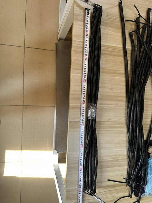
Why Do Coiled Cable Drawings Cause Quotation Errors?
The same phrase can describe different physical conditions. One buyer may use extended length to mean the normal operating reach, while another may mean the furthest temporary stretch. A supplier may measure relaxed length between the ends of the coil body, but the buyer may expect the straight tails to be included. Without named reference points, both parties can report different values while believing the cable meets the request.
A drawing should remove those assumptions. It does not need to be a complex engineering document, but it must show the installed geometry and how the finished sample will be inspected.
Which Dimensions Should Buyers Mark?
| Drawing item | What to define | Why it matters |
|---|---|---|
| Relaxed coiled length | Measurement points and cable condition. | Provides the baseline for storage and dimensional inspection. |
| Normal working extension | The reach used during ordinary operation. | Helps prevent unnecessary connector load. |
| Temporary maximum extension | Only when the application has an occasional longer reach. | Separates an exceptional condition from daily use. |
| Coil outside diameter | Maximum diameter and available installation space. | Controls fit inside a holder, housing or equipment route. |
| Cable outside diameter | Finished jacket diameter or design constraint. | Affects coil geometry, handling and connector entry. |
| Coil pitch | Gap or contact condition between turns. | Influences overall length, appearance and handling. |
| Left straight tail | Start and end measurement points. | Supports routing at the first termination. |
| Right straight tail | Define independently from the left side. | The two ends often serve different mounting conditions. |
| Exit direction | Tangential, axial or application-specific orientation. | Prevents twisting or interference near the device. |
| Connector envelope | Body, latch, overmold and keep-out dimensions. | Confirms fit inside the installed assembly. |
| Connector orientation | Keying and angular relationship to the coil. | Reduces assembly and operator-routing problems. |
| Pinout | Every conductor, shield and drain-wire termination. | Defines the electrical assembly rather than only its shape. |
How Should Relaxed Length Be Measured?
Short answer: define the cable state, conditioning period and reference points before recording the value. A coil measured immediately after extension may not match the same coil after resting. Packaging restraint and temperature can also affect the observed shape, so the buyer and supplier should use the same agreed method.
The drawing should say whether relaxed length includes straight tails and connector bodies. If the coil body alone is controlled, show exactly where the first and last turns begin. For batch inspection, record the agreed sample size and acceptance method instead of relying on a single photograph.
Working Extension Is Not the Same as Maximum Stretch
The normal working extension should represent the reach used by the operator or moving equipment. It is the more useful value for reviewing handling and connector load. Maximum stretch should be treated as a separate, temporary condition when the application genuinely requires it.
Do not choose an extension ratio from a generic catalog and apply it to every design. Conductors, shielding, jacket, cable diameter, coil dimensions and processing all influence the finished behavior. Review the sample in the actual movement direction.
How Should Tolerances Be Assigned?
Not every drawing value needs the same tolerance. Dimensions that control equipment fit, connector mating or routing deserve clear inspection limits. Other values may be references used to describe the design. Marking every value as critical can increase inspection effort without improving the application.
Discuss which dimensions are checked on every unit, which are sampled by batch and which are verified only during first-article approval. The tolerance should match the measurement method and the real installation need.
Connector Orientation and Pinout Belong on the Same Drawing
A mechanically correct coil can still be unusable when the connector key, cable exit or pinout faces the wrong direction. Include the mating connector, pin numbering convention and a view that makes orientation unambiguous. When shielding is involved, show the drain wire and shell or ground termination rather than placing that information only in an email.
For connector-entry questions, also review the TPU coiled cable strain relief and overmolding guide.
Sample Approval Checklist
- Confirm all measurement points against the approved drawing.
- Record relaxed length in the agreed cable condition.
- Check normal working extension in the intended direction.
- Verify coil OD, cable OD, pitch and installation clearance.
- Measure left and right straight tails separately.
- Check connector identity, orientation, mating fit and locking.
- Verify pinout, continuity, shield and drain-wire termination where applicable.
- Observe return behavior after an agreed extension sequence.
- Inspect the sample after packing and unpacking.
Common Drawing Mistakes
- Using one overall length without naming the cable condition.
- Calling temporary maximum stretch the normal working extension.
- Omitting the measurement points for relaxed length and straight tails.
- Showing the connector model but not its orientation or mating part.
- Keeping the pinout in a separate message that can be missed during revision control.
- Applying tight tolerances to every value without an inspection reason.
- Approving dimensions before checking the cable inside the device or fixture.
Buyer Checklist
- Application and equipment installation photos.
- Relaxed length, working extension and any temporary maximum extension.
- Coil OD, cable OD, pitch and available space.
- Both straight-tail lengths and exit directions.
- Conductor count, gauge, shielding and pinout.
- Connector and mating-part numbers with orientation.
- Critical tolerances and measurement method.
- Sample quantity, annual demand, labeling and packaging.
Related Products and Resources
Compare test instrument TPU coiled cables, review the real batch length inspection case, or download the TPU RFQ and sample approval worksheets.
Upload RFQ
Your drawing does not need to be complete before the first review. Upload a sketch, equipment photo, sample dimensions or connector information so the measurement method can be clarified before sampling.
FAQ
Should the drawing use relaxed length or extended length?
Use both, but label the cable condition and measurement points. The normal working extension should be separate from any temporary maximum extension.
Can a physical sample replace a drawing?
A sample helps describe dimensions and handling, but hidden wiring, materials, tolerances and acceptance criteria still need documented confirmation.
Is coil pitch always a critical inspection dimension?
Not always. Treat it as critical when it affects fit, appearance or operation; otherwise it may be a reference controlled through other finished dimensions.