
Quick Answer
An emergency stop coiled cable should be specified from the complete equipment circuit, not selected by coil appearance alone. Before requesting a sample, confirm the circuit function, conductor count and gauge, connector models, pinout, relaxed length, normal working extension, straight-tail lengths, cable exit direction, operating environment and equipment-level acceptance method. The coiled cable is one component of the control system; the machine builder remains responsible for validating the complete safety function and applicable requirements.
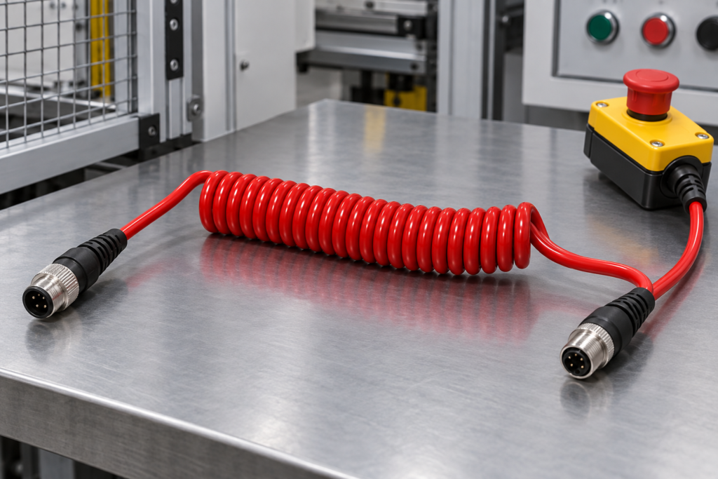
Buyers comparing a custom cable should start with the Emergency Stop and Safety Tether Coiled Cable product page, then review the wider range of custom TPU coiled cables.
Why This Cable Requires a Project-Specific Review
Emergency-stop pendants, interlock devices and safety tether connections often move between a parked position and an operator working position. A coiled construction can keep excess cable compact, but the coil also creates return force. If the working extension is too short, the operator may pull against the connector or enclosure. If the cable is too long or has weak recovery, it may hang into the equipment area.
The electrical design matters just as much as the mechanical reach. A cable may carry multiple control conductors, monitored circuits or separate device functions. The supplier should not guess the pinout, contact assignment, circuit behavior or acceptance standard from a photo.
1. Define the Safety-Control Application
State where the cable is installed and what it connects. Useful information includes:
- Machine, lifting equipment, test station or mobile platform type
- Handheld pendant, pull switch, interlock or tether device
- Fixed and moving connection points
- Normal operator position and maximum intended reach
- Existing mating devices or reference cable
Application context helps the manufacturer review routing, return force, connector retention and exposure risks. It does not replace the buyer’s circuit drawing or equipment-level validation.
2. Confirm Circuit Function and Conductor Construction
Provide the conductor count, conductor size, circuit function and any identification requirement. Do not describe the cable only as “two-core” or “multi-core” if the contact assignment is important.
For each circuit, confirm:
- Voltage and current requirement
- Contact or signal function
- Conductor gauge or required resistance limit
- Color identification or numbering
- Protective conductor, drain wire or shield requirement
The cable construction must be reviewed together with coil diameter and extension. Adding conductors or increasing conductor size can change cable diameter, flexibility and return behavior.
3. Provide Connector Models and Pinout
Send the connector manufacturer, model, mating part and pinout at both ends. Include photographs when an existing connector is available, but do not rely on the photograph alone to define contact numbering.
The RFQ should also state:
- Keying and orientation
- Locking or retention method
- Cable exit direction
- Overmold, boot or strain-relief requirement
- Open-end preparation when no connector is fitted
Connector retention and cable exit should be checked on the actual equipment during sample approval.
4. Separate Normal Working Reach From Maximum Stretch
The maximum distance a coil can be pulled is not the correct daily working length. Define at least four dimensions:
| Dimension | Buyer input |
|---|---|
| Relaxed coil length | Storage length without external load |
| Normal working extension | Distance used during routine operation |
| Temporary maximum extension | Occasional reach, subject to sample review |
| Straight tails | Length and exit direction at both ends |
Also specify coil outside diameter and available installation space. Use the TPU coiled cable drawing and dimensions checklist to prepare measurement points before quotation.
5. Review Return Force at the Equipment
Return force should be assessed in the installed arrangement. A cable that looks acceptable on a table may still pull on a pendant, connector or mounting point when routed around equipment.
During sample review, check whether the cable:
- Reaches the normal operator position without excessive pull
- Returns without striking or snagging equipment
- Remains clear of moving mechanisms
- Does not rotate the connector or load the cable exit
- Parks in the intended location after use
Do not approve the cable from maximum extension alone.
6. Describe the Operating Environment
List the actual exposure rather than requesting a generic “industrial cable.” Relevant conditions may include abrasion, oil or cleaning contact, outdoor use, repeated handling, sunlight, low temperature, heat sources and contact with sharp edges.
Any required material, ingress or compliance target should be supplied as a project requirement and verified at the complete assembly or equipment level. Application wording alone does not prove certification.
7. Agree on Sample Tests
A practical sample-approval plan can include:
- Continuity and pinout inspection
- Project-defined electrical checks
- Relaxed length, working extension and straight-tail measurement
- Connector fit, keying and retention review
- Strain-relief and cable-exit observation
- Return behavior in the installed position
- Appearance, marking and packaging verification
The Testing and Quality Equipment page explains which checks should be agreed before production. Buyers can also use the TPU coiled cable sample approval worksheet.
8. Define Revision and Traceability Information
Control the drawing revision, pinout revision, connector part numbers, approved sample and label content. If several variants share a similar appearance, packaging and product labels should identify the correct version.
The purchase order should reference the approved specification rather than a general product name.
9. Confirm MOQ, Sample Quantity and Packaging
MOQ and lead time depend on conductor construction, TPU material, connector availability, tooling, inspection, marking and packaging. Ask for them after the technical configuration is clear.
State:
- Sample quantity
- Trial order quantity
- Estimated annual demand
- Unit packaging
- Connector protection
- Label and carton-mark requirements
Common RFQ Mistakes
- Giving only a maximum stretched length
- Omitting the normal working extension
- Sending connector photos without part numbers or pinout
- Treating the cable as proof of the complete safety function
- Leaving cable exit direction and straight tails undefined
- Approving appearance without installed-equipment checks
- Mixing several revisions under the same label
Buyer Checklist
- Equipment and safety-control application
- Circuit function, voltage and current
- Conductor count, gauge and identification
- Connector models, mating parts and pinout
- Relaxed length and normal working extension
- Temporary maximum extension
- Straight tails and cable exit directions
- Operating environment
- Sample checks and equipment-level approval owner
- Quantity, revision, labels and packaging
What to Send in Your RFQ
Send the equipment drawing or photos, circuit and pinout, dimensions, connector information, movement path, environment, sample quantity, annual forecast and packaging requirement. If the final drawing is not ready, mark approximate values clearly and identify the items that still require engineering confirmation.
Upload your emergency stop coiled cable RFQ for specification review.